
Continuous SWIR Inspection for Moving Materials
SWIR Linescan Imaging
Build continuous high-resolution SWIR images of moving products, wafers, webs and materials. Pembroke Instruments supplies InGaAs SWIR linescan cameras, optics, illumination and application guidance for high-speed industrial inspection and sorting.
- Inspect moving material continuously rather than frame-by-frame
- Reveal silicon, moisture, polymer, coating and organic-material contrast
- Synchronize acquisition to conveyors, stages and production equipment
- Get help defining line rate, field of view, illumination and integration
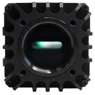
LiSa Linescan SWIR Camera
See SWIR Linescan Imaging in Action
LiSa SWIR Linescan Imaging Video
Why Area-Scan Imaging Is Not Always Enough
Inspect Continuous Material Without Breaking It into Separate Frames
A conventional area-scan camera captures a complete rectangular image in one exposure . A linescan camera instead uses a linear detector with hundreds or thousands of pixels in one row. Each exposure recor ds one narrow slice across the target.
The detector supplies the X dimension. Motion of the product, conveyor, web or scanning stage supplies the Y dimension. Software stacks thousands of successive lines into a continuous 2-D image.
This geometry is ideal for rolls, webs, wafers, conveyor sorting and production processes where material already moves past a fixed inspection point.
Why Add SWIR?
- Image through silicon at suitable wavelengths
- Detect water and moisture differences
- Separate polymers and materials
- Inspect coatings, adhesives and sealants
- Add contrast in food and agricultural inspection
Primary Applications
Where SWIR Linescan Imaging Adds Value
Silicon Wafer Inspection
Inspect wafers and substrates for cracks, edge damage, inclusions and selected subsurface structures.
Semiconductor inspection →Food & Agricultural Sorting
Use SWIR contrast associated with moisture, drying, foreign material and composition on moving conveyors.
Machine vision →Plastics & Recycling
Exploit wavelength-dependent po lymer contrast for automated sorting and recycling.
Material identification →Moisture & Coatings
Inspect moisture variation, coating coverage, adhesives and sealants across moving material.
Web & Roll Inspection
Inspect paper, film, textiles, foil, battery materials and other continuous webs across their full width.
Photovoltaic Inspection
Inspect silicon solar cells for cracks, process defects and non-uniformities during production.
Defect Detection
What Can a SWIR Linescan Camera Reveal?
- Cracks and internal silicon features
- Moisture variation
- Foreign material in food products
- Polymer and material differences
- Missing or uneven coatings
- Web and photovoltaic defects
Sample testing is often the fastest path
Provide the material, inspection width, smallest defect, line speed, working distance and wavelength constraints.
Request Application ReviewLiSa Linescan SWIR Camera
LiSa Technical Specifications
The LiSa uses th e NIT NSC2301 InGaAs sensor with a 2048 × 1 line format and is designed for high-speed SWIR linescan inspection and machine-vision integration.
| Specification | LiSa |
|---|---|
| Sensor | NSC2301 |
| Detector material | InGaAs |
| Resolution | 2048 × 1 pixels |
| Pixel size | 8 × 14 µm | 8 × 200 µm |
| Spectral response | 0.9 to 1.7 µm | Response | Linear — Low, Medium & High Gain |
| Modes | ITR, IWR, ROI |
| Quantum efficiency | >80% |
| Full-frame rate | >110 kHz |
| Minimum integration time | 1 µs; controlled by camera register or trigger width |
| Trigger | Internal / External (LVTTL), Software Trigger, Trigger over CameraLink |
| Trigger delay | User-selectable |
| Partial reading mode | Region of Interest (ROI), user-selectable in steps of 8 pixels; maximum FPS increases with reduced ROI |
| Read-out noise | High gain (CDS): <90 e−; Medium: <370 e−; Low: <2200 e− |
| Dynamic range | High gain (CDS): 55 dB typical; Medium: 62 dB typical; Low: 66 dB typical |
| Control | GenICam / GenCP |
| Output | CameraLink Base; 8/10/12/14-bit pixel formats |
| Output geometry | 1X_1Y / 1X2_1Y / 1X3_1Y |
| Camera power | <4 W |
| TEC cooling power | User-selectable: Off; Low <1 W; Medium <2 W; High <5 W |
| Operating temperature | −40 to +71 °C |
| Size (W × H × L) | 45.4 × 75 × 58 mm |
| Weight | 280 g |
| Lens mount | C-Mount |
| Control protocol | GenCP (GenICam) compliant |
| NIT software | NITGenicamControlTool — Windows, camera control only |
Camera Selection
Match the Imaging Architecture to the Requirement
| Requirement | Starting Point | Why | Resource |
|---|---|---|---|
| Continuous web/conveyor | LiSa SWIR linescan | Continuous image from controlled motion | SWIR cameras |
| Stationary/full-frame imaging | Area-scan SWIR | Complete 2-D frame without target motion | Compare cameras |
| Detailed material ID | SWIR hyperspectral | Many wavelength band s for classification | Hyperspectral |
| High magnification | SWIR microscope | Optimized magnification and positioning | Microscopes |
Featured Solution
LiSa SWIR Linescan Camera
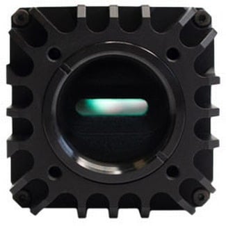
LiSa is designed for high-speed InGaAs line imaging where SWIR material contrast and production throughput both matter.
- 2048-pixel line format
- SWIR InGaAs response
- High-speed acquisition
- External synchronization
- Industrial integration
Build th e Complete Inspection System
Six Requirements to Define Before Selecting a Camera
1. Smallest Defect
Define the smallest feature that must be detected.
2. Inspection Width
Define the field of view across the target.
3. Line Speed
Provide conveyor speed and desired sampling.
4. Wavelength & Lighting
Match illumination to the required material contrast.
5. Mechanic al Geometry
Confirm working distance, lens and available space.
6. Interface & Software
Define triggering, frame grabber, SDK and processing needs.
SWIR Illumination & Accessories → Integration & Calibration →
Pembroke Application Support
Move from Camera Specifications to a Working Linescan Setup
Pembroke Instruments can help evaluate line rate, pixel size, optics, illumination, field of view, working distance, triggering, software and mechanical integration—and determine whether linescan, area-scan or hyperspectral SWIR is the best approach.
Request a Camera RecommendationFrequently Asked Questions
SWIR Linescan Imaging FAQ
How does a SWIR linescan camera create a 2-D image?
It records one line across the target while controlled motion supplies the second dimension. Software stacks the lines into a continuous image.
When is linescan better than area scan?
Linescan is especially effective for continuously moving webs, conveyors, wafers and scanning stages.
Why use SWIR instead of visible linescan?
SWIR can reveal silicon transmission, moisture, polymer, coating and organic-material contrast that may be weak or invisible in RGB imaging.
How is the required line rate determined?
Line rate depends on material speed and the desired sampling distance in the direction of travel.
Should the conveyor use an encoder?
An encoder is valuable when speed varies or accurate geometry and defect coordinates are required.
When should I use SWIR hyperspectral imaging?
Consider hyperspectral when detailed spectral material identification is more important than conventional defect or contrast imaging.
Request Technical Guidance or Pricing
Tell Us What You Need to Inspect
Include the material, inspection width, smallest feature or defect, conveyor speed, working distance, wavelength or illumination constraints, interface and software requirements.
Request a QuoteStart a Technical Discussion