Microscopic temperature measurement • Industrial and research
TM-60D Thermal Imaging Microscope: Two Lenses, One Complete Inspection System
Inspect PCB assemblies, IC packages and small devices with two included thermal lens configurations: a 125 µm nominal spatial-resolution standard lens for wider views and a 25 µm nominal spatial-resolution macro lens for fine-detail inspection. Capture radiometric thermal images and track heat during operation.
Find the source: pinpoint abnormal heating while electronics operate.
Measure and compare: capture temperature maps, video and time-dependent trends.
Build for your sample: camera, both lenses, stage, mount and software.
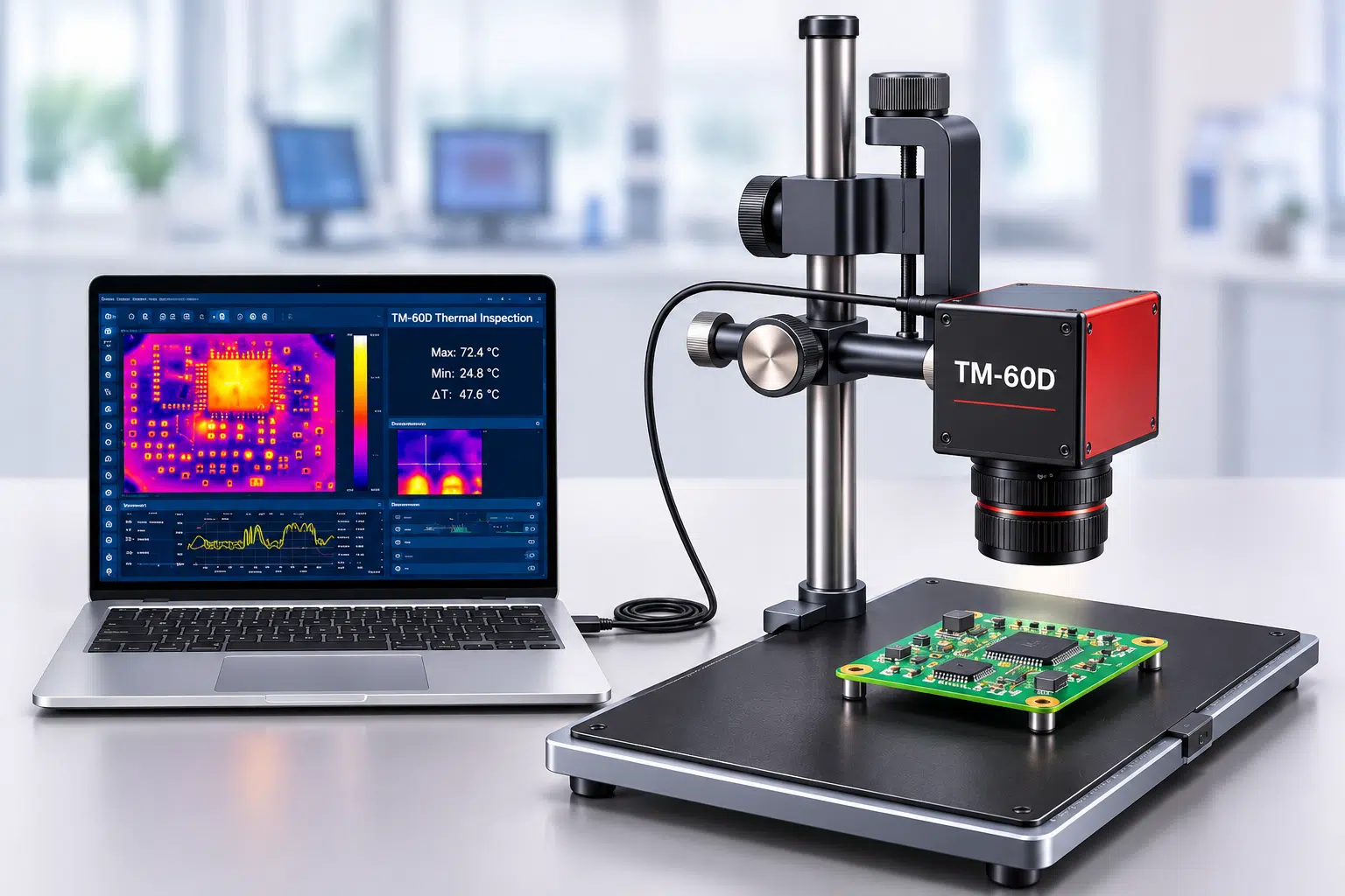
TM-60D thermal imaging microscope system shown inspecting a PCB
640 × 512LWIR detector format
125 / 25 µmNominal standard / macro lens spatial resolution*
−20 to 550°CSpecified measurement range
RadiometricTemperature video and analysis
See the complete solution
A Microscope Designed for Thermal Investigation
More than a camera: an integrated measurement platform that can be configured for the working distance, field of view and detail your application requires.
TM-60D thermal microscope system for PCB thermal inspection
From a hot spot to an engineering answer
640 × 512 LWIR thermal camera
Two lenses supplied: standard wide-field lens and 50 mm macro lens
Choose Wide-Field Context or 25 µm Fine-Detail Imaging
Switch between the supplied standard and macro optics to examine an entire region or zoom in on localized heating. Both configurations use the same 640 × 512 radiometric LWIR detector.
125 µm
Standard Lens — Wide-Field Inspection
48.7° × 38.6° field of view. Useful for locating hot components, comparing neighboring devices and surveying larger circuit-board regions. Manufacturer-listed measurement distance: 4–200 cm.
100 mm example: calculated sampling is 141.4 × 136.8 µm/pixel, so nominal 125 µm should not be read as a universal 100 mm value.
8.8° × 7° field of view. Intended for localized heat patterns in IC packages, traces, power devices and small electronic features. Reported macro working distance: 60–100 mm.
100 mm example: calculated sampling is 24.0 × 23.9 µm/pixel, consistent with the nominal 25 µm designation.
Spatial Resolution, Temperature Accuracy and Emissivity
Good thermal microscopy requires more than a small pixel-size number. The optics determine how much of the sample is represented by each detector pixel; temperature measurement also depends on target size, focus and surface properties.
Spatial sampling vs. measurement spot
A nominal 25 µm image sampling figure does not establish that a 25 µm feature can be measured to the stated absolute temperature accuracy. A target usually needs to cover multiple pixels for dependable quantitative readings.
Emissivity and reflected radiation
Set emissivity by area from 0.1 to 1.0 and account for reflective metal surfaces. For PCB and semiconductor work, compare regions with consistent surface finish and use suitable reference methods where quantitative accuracy matters.
Working distance and field of view
The macro lens provides a narrower view for fine-detail inspection; the standard lens provides broader scene context. Share your device dimensions and smallest feature of interest so the optical configuration can be checked before purchase.
Radiometric analysis workflow
From Live Thermal Images to Temperature Evidence
Capture a thermal image, identify a hot region, and compare maximum, minimum and average temperatures. Use the available radiometric JPG output for thermal image analysis and MP4 for video documentation.
Live thermal observation at up to 25 Hz
Maximum, minimum and average temperature measurements
Area-based emissivity adjustment (0.1–1.0)
Radiometric JPG still-image output and MP4 video files
System configuration can include thermal analysis and electrical synchronization options; confirm exact software, interfaces and supported functions when quoting
Adjust emissivity and document operating conditions.
Record temperatures and export images or video for review.
Illustrative workflow; available analysis features depend on supplied software configuration.
Engineering FAQs
Common Questions About TM-60D Thermal Microscopy
Does the TM-60D come with both lenses?
Yes. The Pembroke TM-60D package described on this page includes both the standard lens (nominal 125 µm) and the 50 mm macro lens (nominal 25 µm).
Does 25 µm mean a 25 µm hot spot can be measured accurately?
Not necessarily. Nominal spatial resolution or pixel sampling is different from minimum target size for accurate temperature measurement. Ask for a target-size and calibration assessment for your application.
Which lens is better for PCB fault isolation?
Use the standard lens to locate heating over a wider PCB region; use the macro lens to investigate smaller components and local gradients at an appropriate working distance.
Can I measure temperatures on reflective metal?
Reflective surfaces can cause emissivity and reflected-temperature errors. Use appropriate emissivity settings and a validated reference method when absolute accuracy matters.
What information helps specify the system?
Provide sample dimensions, smallest feature, desired working distance, temperature range, and whether radiometric recording or synchronized electrical measurements are required.
Applications that benefit from thermal microscopy
Find Problems That Visible Inspection May Miss
Use spatially resolved temperature information to narrow the search for defects, compare operating conditions and accelerate development.
01
PCB & Electronics
Locate hot spots, short circuits, leakage paths and abnormal component heating during powered testing.
Thermal microscopy helps identify heat patterns across components, traces, packages and localized defect regions. Examine the response during power-up, load changes and comparative tests.
Spatial detail depends on the optics, working distance, measurement conditions and sample. The standard and macro configurations are described by nominal 125 µm and 25 µm spatial resolution respectively. Actual object-space pixel size varies with working distance and must not be confused with minimum accurately measurable temperature spot size.
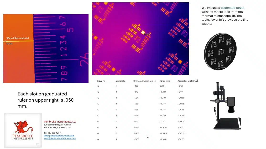
Resolution example from Pembroke thermal microscope product materials
What Is Causing the Unexpected Heat?
Send us your sample dimensions, target feature size, desired field of view and temperature range. We can recommend a practical thermal microscope configuration.
60–100 mm (reported; confirm focus range for application)
Focus
Manual
Manual
Frame rate
25 Hz
25 Hz
Thermal sensitivity (NETD)
<50 mK at 25°C, F/1.0
<50 mK at 25°C, F/1.0
Object temperature range
−20°C to +550°C
−20°C to +550°C
Temperature accuracy
±2°C or ±2% (−20°C to 120°C); ±3% (120°C to 550°C), per supplied comparison
Same
Emissivity setting
0.1–1.0, adjustable by area
0.1–1.0, adjustable by area
Thermal measurement
Maximum, minimum and average temperature
Maximum, minimum and average temperature
Still / video export
Radiometric JPG / MP4
Radiometric JPG / MP4
Operating temperature
−10°C to +55°C
−10°C to +55°C
*125 µm and 25 µm are nominal lens-configuration spatial-resolution figures. The 100 mm sampling figures are geometric calculations supplied in the comparison worksheet, not independently verified measurement-spot specifications. Detecting a small thermal feature is not the same as measuring its absolute temperature accurately. Final performance depends on focus, working distance, emissivity, reflected radiation and measurement conditions.
Request pricing and application guidance
Get a Thermal Microscope Recommendation and Quote
Describe what you need to inspect and the level of detail you need. Pembroke Instruments can help choose the camera, included lenses, stage and measurement software.
If the contact form does not appear in this window, open the inquiry in a new tab. The selected application is included in the inquiry URL; automatic field filling requires compatible Gravity Forms configuration.